A Schlenk flask is a specialized reaction vessel designed for operations under inert gas or vacuum.[1][3] In its standard form, it combines a round-bottom or Kjeldahl-shaped body with a side arm fitted with a high-vacuum valve or stopcock, allowing the vessel to be connected to and isolated from a Schlenk line.[1][4] In modern laboratory practice, it is one of the most important tools for handling air- and moisture-sensitive compounds in organometallic chemistry, catalyst preparation, and advanced synthetic work.[2][3]
1. Quick Definition
A Schlenk flask (or Schlenk tube, depending on size and form) is a borosilicate glass reaction vessel with a sidearm valve designed for controlled atmosphere work.[1][3][6] Its primary function is to allow repeated evacuation and refill with inert gas, so that sensitive reagents can be manipulated under nitrogen or argon rather than exposed to ambient air.[1][9]
Unlike an ordinary round-bottom flask, a Schlenk flask is not just a container. It is part of a broader atmosphere-control system.[3][9] The side arm provides controlled access to the vacuum/inert-gas manifold, while the main neck remains available for reagent charging, septum sealing, or connection to auxiliary glassware.[4][8]
2. Core Physical Logic
The operating logic of the Schlenk flask centers on controlled atmosphere exchange.[9] By connecting the side arm to a dual-manifold Schlenk line, the vessel can be evacuated and then backfilled with inert gas in a repeated evacuate–refill cycle.[9] Each cycle reduces the concentration of oxygen and moisture inside the vessel, eventually reaching levels suitable for air-sensitive reactions.[1][9]
The body geometry also matters. A round-bottom or Kjeldahl-shaped Schlenk flask distributes stress more evenly under reduced pressure than a flat-bottom vessel and performs better during heating and cooling.[6][13] In practical use, the flask body, the side arm, the valve, and the main neck all work together as a single atmosphere-control system.[4][5]
Glassblower’s Note
PTFE stopcocks are designed for grease-free operation. In normal use, adding vacuum grease to a PTFE plug does not improve sealing and may instead contaminate the valve pathway or introduce residue into sensitive reactions. If a PTFE stopcock stops sealing properly, the more likely causes are wear, a damaged sealing surface, or an aging O-ring rather than lack of lubrication.[5]
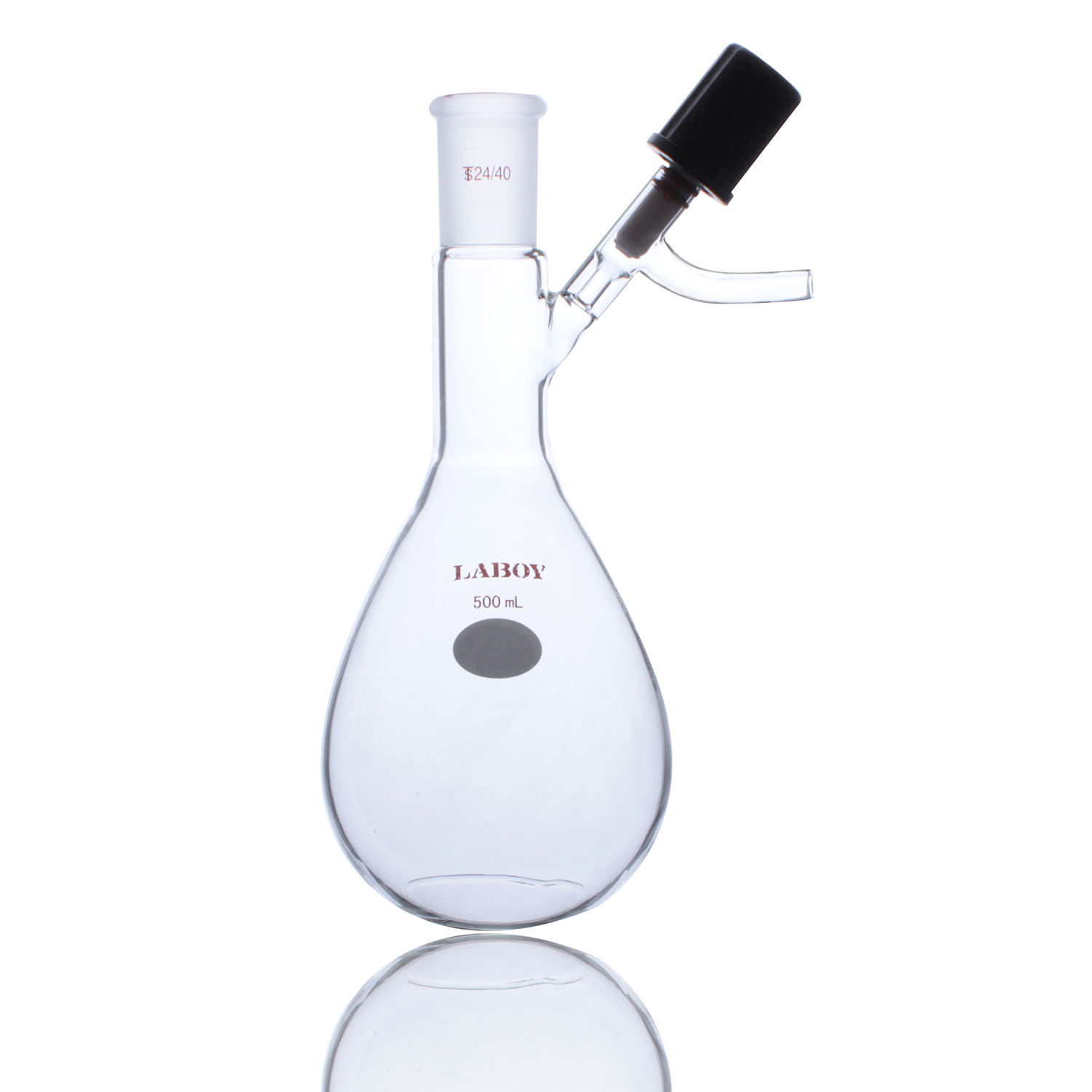
3. Structural Anatomy
A standard Schlenk flask contains four essential structural elements:[4]
- Main neck: Usually a standard taper joint such as 14/20, 19/22, or 24/40, used for charging reagents, inserting accessories, or sealing the vessel.[6]
- Reaction body: Typically round-bottom or Kjeldahl-shaped, made of borosilicate glass and designed to tolerate vacuum and thermal cycling.[6][13]
- Side arm: An angled outlet fused to the body, providing controlled connection to vacuum or inert gas.[4][7]
- Valve or stopcock: Usually PTFE or glass, used to isolate the flask from the line or open it to the system as required.[5]
        ┌─────────────────────────────────────┐
        │          Main Neck                 │
        │     standard taper joint          │
        └────────────────┬───────────────────┘
                         │
    ┌───────────────────▼───────────────────┐
    │       Reaction Body (Round /          │
    │       Kjeldahl / Pear-Shaped)         │
    │   borosilicate heavy-wall chamber     │
    └───────────────────┬───────────────────┘
                         │
        ┌───────────────▼────────────────┐
        │            Side Arm            │
        │    connection to Schlenk line  │
        └───────────────┬────────────────┘
                         │
        ┌───────────────▼────────────────┐
        │        PTFE or Glass Valve     │
        │   isolation / evacuation / gas │
        └────────────────────────────────┘
4. Technical Specifications
For joint sealing, taper compatibility, and valve-side connection logic, it is useful to read this alongside a broader guide to laboratory glass joints and inert-atmosphere assembly practice.
Lab Practice Note
A reliable inert atmosphere usually requires at least three evacuate–refill cycles.[9] After oven drying, many chemists connect the warm flask directly to the line while it is still cooling so that it does not draw humid room air back inside.[9] When reagents must be added during a reaction, a rubber septum with syringe or cannula transfer is usually more reliable than repeatedly opening the vessel to the room.[8][17]
5. How a Schlenk Flask Works in Practice
In actual laboratory use, the Schlenk flask serves as the terminal reaction vessel on a Schlenk line.[3][9] After connection, the flask is evacuated, backfilled with inert gas, and then isolated or reopened as needed. This makes it possible to dry solvents, degas solutions, store reactive intermediates, or conduct full reactions without exposing the system to atmospheric moisture or oxygen.[9][11]
One of the most important operations performed in a Schlenk flask is freeze–pump–thaw degassing.[11] In this procedure, a solvent is frozen, evacuated, isolated, and then thawed. Repeating the cycle removes dissolved gases efficiently. This method is especially important in organometallic chemistry and other oxygen-sensitive reaction systems.[11][17][18]
6. Safety Limits and Critical Warnings
Although Schlenk flasks are built for demanding work, they are still glass vacuum vessels and must be treated accordingly. A Schlenk flask should never be used if it has scratches, chips, star cracks, or a damaged valve seat.[13][16] Under vacuum, even a small defect may become a stress concentration point and lead to implosion.[13]
It is equally important to remember that Schlenk flasks are designed for vacuum and inert atmosphere work, not for uncontrolled internal pressure. They should not be treated as pressure reactors.[13][15]
Standard protective practice includes careful glass inspection, proper support of the vessel body, eye protection, and cautious handling of cryogenic baths and vacuum lines.[10][13][16] In more hazardous systems, additional barriers such as blast shields may be appropriate.[16]
7. Why Schlenk Flasks Remain Essential
The Schlenk flask remains one of the defining tools of advanced synthetic chemistry because it combines atmosphere control, modularity, and practical usability in a single piece of apparatus.[1][3][9] It is simple in principle but highly refined in function. For chemists working with organometallic reagents, moisture-sensitive catalysts, reactive intermediates, or rigorously dried solvents, it remains one of the most reliable and adaptable vessels available.[2][17][18]
References
- Frank, P. Schlenk Line Safety. 2011: I.1.
- Wang, Jitao, and Song, Licheng. Organometallic Chemistry. Beijing: Higher Education Press, 1989, Chapter 2.
- Frank, P. Schlenk Line Safety. 2011: I.1.
- Frank, P. Schlenk Line Safety. 2011: I.2.
- Frank, P. Schlenk Line Safety. 2011: II.2.1.
- Laboy Glass. Laboy Catalog. 2020: materials description section.
- Frank, P. Schlenk Line Safety. 2011: I.2.
- Frank, P. Schlenk Line Safety. 2011: I.2.
- Frank, P. Schlenk Line Safety. 2011: I.1, I.2.
- Frank, P. Schlenk Line Safety. 2011: I.2.
- Frank, P. Schlenk Line Safety. 2011: Section 7.
- Frank, P. Schlenk Line Safety. 2011: safety warning in Section 7.
- Frank, P. Schlenk Line Safety. 2011: II.2.1.
- Frank, P. Schlenk Line Safety. 2011: II.1.2.
- Frank, P. Schlenk Line Safety. 2011: II.1.
- Frank, P. Schlenk Line Safety. 2011: personal protective equipment section.
- Wang, Zhiyong. Advanced Practical Organic Chemistry Laboratory Tutorial. 2016: 1.3.5.
- Wang, Zhiyong. Advanced Practical Organic Chemistry Laboratory Tutorial. 2016: 1.3.5.
- Wu, Ruofeng, et al. Micro Organic Chemistry Experiments. 1998: usage notes.