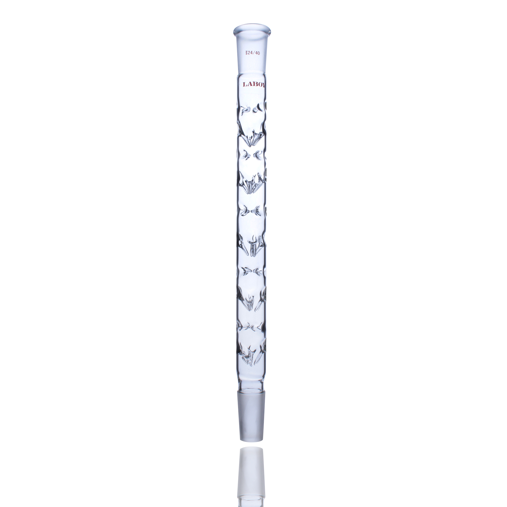
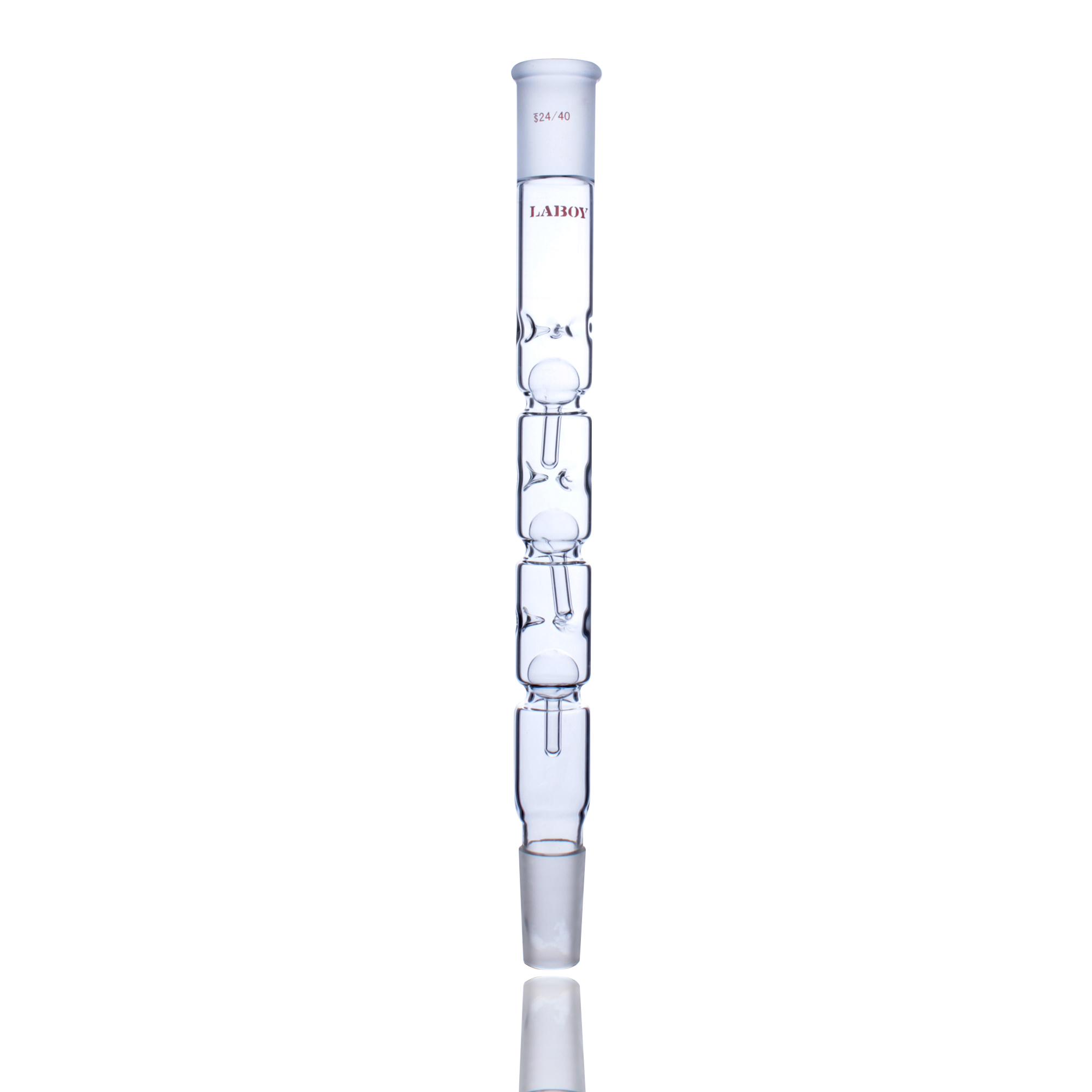
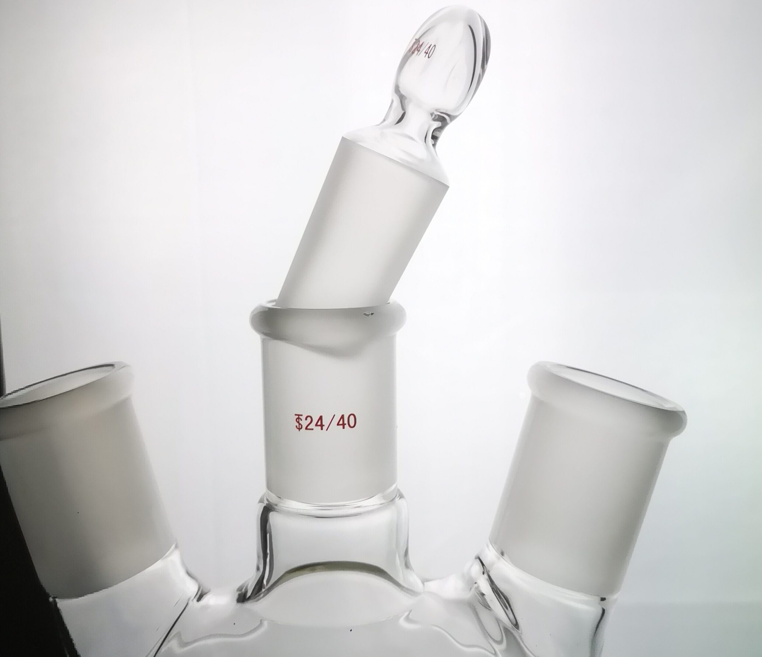
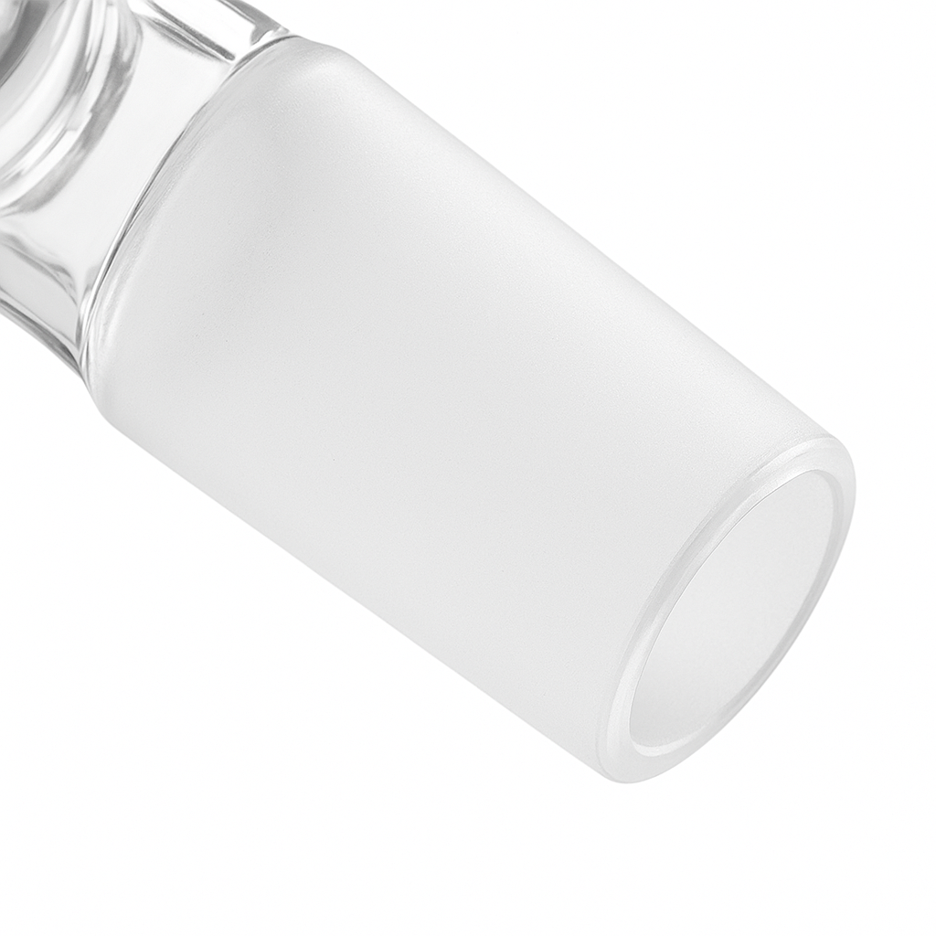
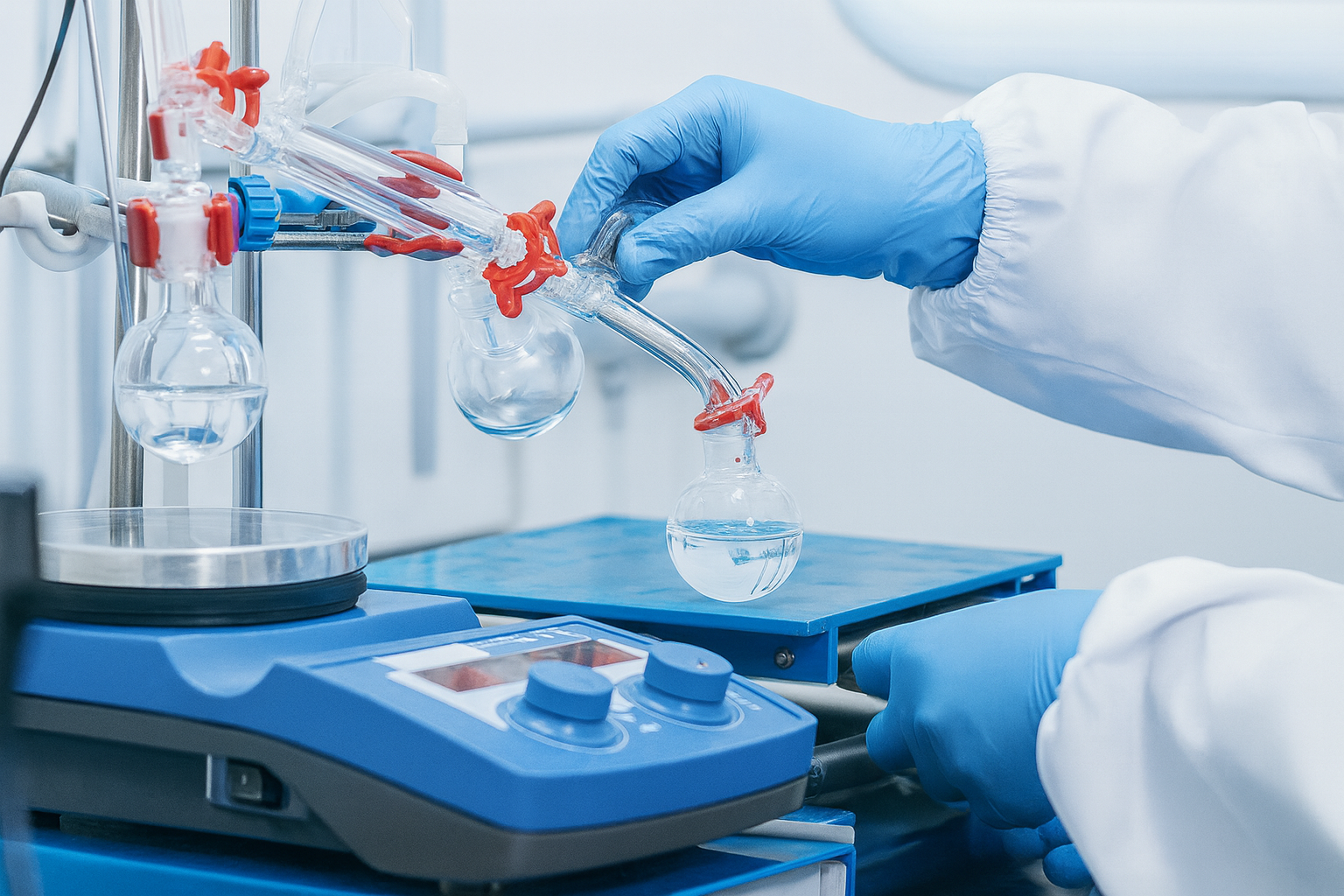
Why Your Vigreux Column Failed: A Glassblower’s Guide | ChemNorth

Article Body

(Intro) A Vigreux column adds surface area, not controllable theoretical plates—and without proper thermal management, it rarely performs the way people expect.

Common Misconceptions: Is Your Vigreux Column Defective?

I’ve been blowing scientific glass for nearly twenty years, and over that time I’ve seen almost every kind of request imaginable. Last week, a long-time client from a local research institute came to my workshop with a Vigreux column I had made.

He pointed at the indentations and asked, “Is there a defect in this column? I’ve seen other brands where the spikes are much denser. Yours seem too sparse. My distillation purity was poor yesterday, and I suspect this column doesn’t provide enough theoretical plates.”

I held the column up to the light. It was a standard Vigreux structure—uniform wall thickness, consistent indentation depth and angle, no visible stress or flaws. There was nothing wrong with the glass itself.

I told him, calmly, “The column isn’t defective. Even if I rebuilt this to look like a hedgehog, your separation probably wouldn’t improve. The effectiveness of a Vigreux column has never depended on how many ‘teeth’ it has.”

That conversation reminded me how often even experienced chemists misunderstand the limitations of the glassware they use every day. From a glassblower’s perspective, here’s why a Vigreux column so often feels like it “isn’t working.”

Recommended Reading: For a clear visual comparison of how Vigreux, packed, and other fractional distillation columns are constructed internally, see our guide: 👉 Inside Fractional Distillation Columns: What’s Really Inside?

The Glassblower’s Perspective on Design

When customizing laboratory glassware, many people assume:

  • More complex structure → More surface area → Better separation.

That intuition isn’t wrong—but it’s incomplete.

Surface Area vs. Turbulence

The inward-facing indentations of a Vigreux column serve only two real functions:

  1. Increase Contact Area: They increase gas–liquid contact area.
  2. Create Turbulence: They disrupt straight vapor flow and introduce turbulence.

What they do not do is magically generate a large number of theoretical plates. By design, a Vigreux column is a low-efficiency fractionating column. If your target separation demands high plate counts, asking for more indentations misses the point. At that stage, you should be using a Packed Column, not trying to force extra performance out of a Vigreux.

Why More Indentations Reduce Efficiency

The next question I’m usually asked is: “If you add more rows of indentations, wouldn’t that help?”

In practice, it often does the opposite. From a glassblowing standpoint, indentation density is limited by the need to maintain uniform wall thickness and manage thermal stress. However, overcrowding the internal structure introduces a more serious operational issue.

The Risk of Column Flooding

When vapor flow is partially obstructed by overly dense spikes, refluxing liquid can no longer drain smoothly downward. Instead, liquid becomes trapped and pushed upward by rising vapor. This phenomenon is known as Flooding.

When flooding occurs:

  • Gas–liquid contact turns chaotic.
  • Pressure drop increases significantly.
  • Effective fractionation collapses.

In extreme cases, the distillation stalls entirely. At that point, separation efficiency isn’t just poor—it’s fundamentally compromised.

The Real Culprit: Lack of Insulation & Thermal Management

If the column itself wasn’t the problem, what went wrong with my client’s experiment? I asked one simple question:

“When you ran the column, did you insulate it?”

There was a pause. “You mean dressing it? No—I wanted to see the liquid level.”

That answer explains most disappointing Vigreux results I encounter.

Understanding Internal Reflux

In my experience, the majority of “inefficient” Vigreux columns aren’t failing because of poor glass design. They fail because of poor insulation.

Vigreux columns are thin-walled by necessity. Without insulation, ambient air strips heat from the rising vapor long before it reaches the still head. This creates excessive, uncontrolled internal reflux. While some reflux is essential, reflux driven by room temperature rather than operator control rarely improves separation.

I advised him to try again: wrap the column with glass wool or cotton, or use a vacuum-jacketed alternative. Let vapor travel smoothly to the top, where the reflux ratio can be managed intentionally rather than dictated by heat loss to the lab.

Glass Vigreux distillation column wrapped in white cotton insulation to prevent heat loss, connected to a round bottom flask in a heating mantle.
The Solution in Action: A Vigreux fractional distillation column fully wrapped in insulation material (lagging). This setup illustrates the practical solution for maintaining adiabatic conditions, preventing premature condensation, and ensuring vapor reaches the condenser—crucial for high-boiling point distillations.

3 Expert Tips for Better Distillation Results

Two days later, I received a message: the desired purity had been reached. After decades at the torch, I’d offer three practical recommendations to anyone working with fractional distillation columns:

1. Communicate with Your Glassblower

Before assuming an instrument is defective, discuss the problem. Often the solution isn’t a new column—it’s an extra layer of insulation or a slight adjustment in technique.

2. Choose the Right Tool

Vigreux columns are meant for simple separations. If your components boil within about 10 °C of each other, stop struggling with a Vigreux and switch to a higher-efficiency design, such as a Packed Column.

3. Respect the Physics

Glass geometry is static. Heat input, insulation, and reflux control are not. Focus on the system as a whole, not just the shape of the glass.

Remember: Glass doesn’t decide how well your distillation runs. You do.


FAQ: Common Questions About Vigreux Columns

Q: What is the main disadvantage of a Vigreux column? A: The main disadvantage is its relatively low number of theoretical plates compared to packed columns. It is not suitable for separating compounds with very close boiling points.

Q: Why is my Vigreux column flooding? A: Flooding usually occurs when the vapor velocity is too high or the indentations are too dense, preventing the liquid from draining back down. It can also happen if the heat input is too aggressive.

Q: Do I need to insulate my Vigreux column? A: Yes, absolutely. Without insulation (like glass wool or a vacuum jacket), ambient air cools the vapor too quickly, causing uncontrolled internal reflux and reducing separation efficiency.

About the Author: Zoe.W

With over 20 years of experience in hand-blown glass manufacturing, Zoe.W is dedicated to bridging the gap between craftsmanship and laboratory application. Combining frontline lab feedback with deep industry knowledge, she specializes in solving complex equipment challenges for organic chemistry experiments.

Connect with Zoe: Email |

Inside a Fractional Distillation Column: A Visual Guide to 4 Lab Types

Hemple Packed Column
Vigreux Columns
Laboy Glass Snyder Distillation Column With 24/40 Joints 300mm In Overall Height
Bulb-type Columns
Spinning Band Columns

From the outside, a fractional distillation column doesn’t look like much. It’s usually just a piece of glass or metal sitting between a boiling flask and a condenser. But if you’ve ever tried to separate two liquids with similar boiling points, you find out quickly that what happens inside the column matters a lot.

Textbooks usually show a single generic drawing and call it a day. In real laboratories, however, a “fractional column” can refer to several very different designs, each with its own internal structure and personality.

This article looks inside the four types of lab-scale fractional columns you’re most likely to encounter:

  • Vigreux columns
  • Packed columns
  • Bulb-type (Hempel-style) columns
  • Spinning band columns

We aren’t looking at equations here. We are looking at the physical reality: What does it actually look like inside, and what does that mean for your separation efficiency?


1. Vigreux Columns: The “Teeth” Design

Vigreux Columns

A Vigreux column is often the first fractional column a student handles. If you hold it up to the light, the internal structure is immediately obvious.

Instead of a smooth bore, the inner wall features rows of glass indentations pressed inwards. They look like little “teeth” or steps sticking into the center of the column.

Key Features:

  • No loose packing
  • No trays
  • No moving parts

How it works: During a distillation, vapor rises from the boiling flask into the column. The cooler glass teeth provide surface area for vapor to condense. This condensate forms a thin film and runs back down the column as reflux.

Each of those teeth acts as a small interruption in the vapor’s journey upward. The continual condensation and re-evaporation along the wall gives you more effective separation than a simple straight adapter, without making the hardware complicated.

The Verdict: Vigreux columns are tough, easy to clean, and forgiving to beginners. The trade-off is that their separation efficiency is modest compared to more specialized designs.

If you’re curious why the familiar “teeth” design adds less separation than many people expect, we take a closer look here:
Why Vigreux Columns Are Less Efficient Than they Look


2. Packed Columns: Maximizing Surface Area

Hemple Packed Column

From the outside, a packed column can look almost identical to a plain glass tube. The difference is obvious once you look through the bore: it’s full of packing material.

What’s Inside: Inside, you’ll find small pieces of material designed to maximize surface area, such as:

  • Glass helices or Raschig rings
  • Glass or metal saddles
  • Metal or PTFE mesh rolls

A support at the bottom—usually a frit, a perforated plate, or a plug of glass wool—keeps the packing from falling into the flask.

How it works: When a packed column is running, hot vapor rises through the small channels between packing pieces, while liquid flows downward over the surfaces. Every bit of that surface becomes a site for vapor–liquid contact.

The column doesn’t look “empty” from the inside. It feels more like a dense maze of surfaces coated with thin liquid films, with vapor squeezing through the gaps. That huge internal area is what gives packed columns their high efficiency (often measured in HETP – Height Equivalent to a Theoretical Plate).

The Verdict: The price you pay is sensitivity. Push the heat too hard or let too much liquid accumulate, and the packing can flood, causing pressure drops and performance collapse. Cleaning is also more difficult than with a simple Vigreux tube.


3. Bulb-type (Hempel) Columns: Visualizing the Process

Laboy Glass Snyder Distillation Column With 24/40 Joints 300mm In Overall Height
Bulb-type Columns

Bulb-type, or Synder-style, fractional columns are less common in modern catalogs but remain very popular in teaching and small-scale organic labs.

Looking inside one, you don’t see teeth or loose packing. Instead, you see a vertical chain of glass bulbs joined by narrower necks. Each bulb acts as a small chamber where vapor can expand and liquid can temporarily pool.

How it works:

  1. Vapor enters a bulb, expands, and cools slightly.
  2. Part of it condenses and collects as a liquid layer.
  3. Overflow drains back down through internal paths to the bulb below.
  4. The remaining vapor continues upward to the next bulb.

From the outside, you can literally watch liquid appear and move inside the bulbs as the distillation runs. Each bulb behaves like a visible equilibrium stage. For teaching, this makes concepts like “reflux” and “plates” much less abstract.

The Verdict: Bulb-type columns sit in the middle ground: more effective than a short Vigreux column, but less extreme than optimized packed columns. They are a nice compromise when you want both performance and a clear visual picture of the process.


4. Spinning Band Columns: The High-Performance Choice

Spinning Band Columns

Spinning band columns are what you reach for when you’ve run out of easy options and still need higher resolution to separate close-boiling compounds.

At first glance, they appear to be long, narrow glass columns with a motor housing at the top. Inside the bore, however, is a complex mechanism:

  • A central shaft driven by the motor.
  • A flexible band (metal or PTFE) attached to that shaft, running the length of the column.

How it works: When the column is in use, the motor spins the band at high speed. As vapor rises and condenses on the cooler surfaces, the spinning band actively wipes the condensate into a very thin, uniform liquid film and drags it along the column interior.

Instead of relying on static packing or gravity, a spinning band column actively manages the liquid film thickness. This constant refreshing of the surface allows these columns to reach very high effective plate counts on the lab scale.

The Verdict: The downside is cost, complexity, and maintenance. You have moving parts, seals, and a drive mechanism. For routine teaching, they are overkill; for difficult separations of valuable materials, they are essential.


Quick Comparison: Which Column is Inside Your Lab?

Comparison of Vigreux, bulb-type, packed and spinning-band fractional distillation columns
Column Type Internal Feature Efficiency Complexity Best For
Vigreux Glass “teeth” along the inner wall Low Low Simple distillations, student labs
Bulb-type Series of glass chambers or bulbs Medium Low Visualizing reflux, teaching demonstrations
Packed Beads, mesh, or rings packed in the column High Medium General high-purity distillation work
Spinning Band Rotating helical band inside the column Very high High Close-boiling point separation, analytical work

This comparison is meant to help you recognize what is already sitting on your lab bench. If you are currently shopping for a new fractional distillation column, you may find this practical buying guide helpful: How to Choose the Right Fractional Distillation Column for Your Lab .


Summary: Different Interiors, Same Goal

Although these four designs look very different inside, they are all built around the same simple idea: Make vapor and liquid meet each other as many times as possible on the way up and down the column.

They just achieve this in different ways:

  • Vigreux: Fixed glass indentations.
  • Packed: A bed of small pieces with huge surface area.
  • Bulb-type: Visible chambers for partial equilibration.
  • Spinning band: A mechanically refreshed thin film.

There is no hidden machinery in a fractional distillation column – only surfaces, temperature gradients, and gravity working together.

Once you’ve seen how these interiors are built, many of the usual puzzles in distillation – such as [column flooding], [poor separation efficiency], or [strange temperature profiles] – start to make much more sense.

In practice, watching these columns at work does more to fix the concepts in your mind than any diagram ever will. ChemNorth is here to help bridge that gap between the drawing on the page and the glass in your hands.

The Ultimate Guide to Glassware Joints: Sizes, Compatibility, and Secrets No One Tells You

Have you ever had that moment of quiet despair in the lab?

Your reaction is ready, you reach for a new addition funnel, try to fit it onto your flask, and… it doesn’t fit. Or worse, it fits, but wobbles just enough to make you nervous.

The box says “24 mm standard joint”, so why is one connector long and the other short? Why do some standard taper joints seal beautifully while others always seem to leak?

Glassware is our hardware, yet clear explanations of these joints are strangely rare in textbooks. This lack of clarity leads to real frustration at the bench—especially when you are trying to figure out the critical difference between a 24/40 and a 24/29 joint before a reaction starts.

This guide is ChemNorth’s answer to that confusion. We will map out the main joint types, decode exactly what the numbers (like 24/40) mean, explain the difference between ASTM and ISO standards, and provide a practical compatibility cheat sheet you can rely on.

Types of Laboratory Glassware Joints

Before getting lost in the numbers, it helps to see the whole map. Not all connections are created equal—each joint type has its own “personality” and typical role.

Standard taper glass joint with ground cone and socket connection

Standard Taper Joints

The Workhorse.

  • Conical, ground-glass surfaces (14/20, 24/40, 29/42, NS 24/29, etc.).
  • Main connection on flasks, condensers, adapters, and funnels.
  • Rigid, airtight joint; this guide focuses mainly on these.
Laboy 35/20 spherical ball and socket joint showing angular flexibility

Spherical (Ball & Socket) Joints

The Flexible Gymnast.

  • Rounded “ball” fits into a cup-shaped socket.
  • Allows ~10–15° of angular flexibility.
  • Used on rotary evaporators and long vacuum manifolds.
  • Must be secured with metal pinch clamps.
Laboy flat flange O-ring style glass joint for heavy-duty reactor connections

Flat Flange Joints

The Heavy-Duty Solution.

  • Wide, flat sealing faces clamped with an O-ring.
  • Provides a large opening for reactors and vacuum vessels.
  • Ideal when you need cleaning access or large stirrer shafts.
GL screw thread glass joint with external threads for cap and gasket

Screw Thread (GL) Joints

The Modern Modular Connector.

  • External glass threads plus a plastic cap and gasket.
  • Height-adjustable; no grease required.
  • Common on GL45 bottles and GL14/18/25 adapters.

The Chemnorth Take: While all four types are essential, the one that causes the most headaches is undoubtedly the Standard Taper Joint.

Why? Because of the confusing numbers, conflicting international standards, and joints that claim to be the same size but turn out to be different lengths. In the next section, we’ll peel back the layers of this mystery and solve the compatibility puzzle once and for all.

Standard Taper Joint Dimensions & Sizes Explained

To understand laboratory glassware compatibility, you simply need to decode the two-number designation (written as A/B).

What do the numbers (e.g., 24/40) mean?

  • The First Number (A): Represents the nominal outer diameter (OD) of the joint at its widest point, in millimeters.
  • The Second Number (B): Represents the length of the ground-glass zone (the frosted area), in millimeters.

Examples:

  • 24/40 Joint: Has a nominal width of 24 mm and a ground length of 40 mm.
  • 14/20 Joint: Has a nominal width of 14 mm and a ground length of 20 mm.

Note on Precision: The first number is a “nominal” category. For instance, in a 14/20 joint, technical diagrams often show the actual diameter is slightly larger (e.g., ~14.5 mm) to accommodate manufacturing tolerances and ensure a tight seal.

What does a 1:10 taper mean?

Diagram showing the dimensions of a 14/20 standard taper joint with 1:10 taper, including large-end diameter, small-end diameter, and ground length
Dimensional diagram of a 14/20 standard taper joint manufactured with a 1:10 taper. The drawing shows the nominal diameter, ground length, and the change in diameter along the taper.

Regardless of the size—14/20, 24/40, or 45/50—all standard taper joints share the same 1:10 geometric slope.

So what does “1:10 taper” actually mean? It is not an angle in degrees. Instead, it means that for every 10 mm of length along the joint, the diameter changes by 1 mm. In other words, the cone is very shallow and very consistent.

For example, let’s do the math on a 14/20 joint:

  • Large-end diameter: 14.5 mm
  • Small-end diameter: 12.5 mm
  • Difference: 2.0 mm
  • Ground length: 20 mm

The diameter changes 2.0 mm over a 20 mm length, so the taper is exactly 1:10.

This matters because such a gentle, consistent slope is the secret to the joint’s reliability. It allows the joint to self-center as it is inserted, creating a tight seal without excessive force. More importantly, because the slope is fixed, joints from different manufacturers and different standards remain geometrically compatible, even when their ground lengths are not the same.


ASTM (US) vs. ISO (Europe): Same Taper, Different Lengths

Once we know the taper is fixed at 1:10, the only major variable left is the length of the ground section. This is exactly where the world divides into two camps.

The confusion often stems from one simple question: Why do US and European joints look different if they claim to be the same size?

The answer is geometry. Since the taper is identical and the nominal diameter is the same, ASTM and ISO/DIN standards are simply two different ways of slicing the same 1:10 cone.

1. US Standard (ASTM) — “Full-Length” Joints

  • Typical sizes: 14/20, 24/40, 29/42
  • Traits: Longer ground section with more contact area.
  • Best for: Heavy, vertical glassware (tall condensers, columns, large flasks) where extra mechanical stability is valuable.

2. European Standard (ISO/DIN) — “Medium-Length” Joints

  • Typical sizes: 14/23, 24/29, 29/32
  • Traits: Shorter ground section that is easier to separate and less likely to “freeze” (get stuck).
  • Best for: Routine work where easy disassembly and slightly lower glass cost matter more than maximum support.

ASTM vs ISO Glassware Joints: Difference Between 24/40 and 24/29

Feature US Standard (ASTM) European Standard (ISO/DIN)
Common Name Full-Length Joints Medium-Length Joints
Typical 24 mm Joint 24/40 24/29
Ground Zone Length Longer (40 mm) Shorter (29 mm)
Best For Heavy, vertical assemblies and tall condensers Easy separation and economical glassware

Real-World Compatibility: Can You Mix Them?

This is the most common question we hear:

“I have a European 24/29 flask and a US 24/40 condenser. Can I use them together?”

Short answer: yes, in most routine setups. Because they share the same 1:10 taper and the same nominal 24 mm diameter, a 24/40 joint and a 24/29 joint will usually seal. However, the different lengths create two distinct scenarios you need to watch out for.

Scenario A: Long Male (24/40) + Short Female (24/29)

  • The fit: The long 24/40 male joint reaches further in and may stick out slightly into the flask.
  • The verdict: ✅ Generally safe. The seal is good, but any exposed ground glass inside the vessel can trap residues and make cleaning more annoying.

Scenario B: Short Male (24/29) + Long Female (24/40)

  • The fit: The short 24/29 male joint sits very deep inside the longer 24/40 socket, leaving part of the female ground area unused at the top.
  • The verdict: ⚠️ Use with caution. Deeply seated short joints are more prone to frozen joints, especially without grease or if the setup is heated and cooled repeatedly. Always use a Keck clip to stop the joint from creeping deeper under its own weight.

Chemnorth Pro Tip: When mixing ASTM and ISO joints, ALWAYS use Keck clips. Since the lengths don’t match perfectly, the clip is essential to fix the relative position—preventing short joints from sinking too deep and long joints from wobbling.

For routine organic synthesis—reflux, simple distillation, moderate vacuum—mixing 24/29 and 24/40 is usually acceptable if you handle the glass with care and understand these caveats.

For high vacuum, long, hot runs, or heavy, tall assemblies, it is safer to commit to one standard throughout the setup and avoid mixed-length joints altogether.


The Master Cheat Sheet

This is the part you’ll want to print and tape to the lab wall.

Standard Taper Joint Sizes (Quick Reference Table)

If you just want a ground glass joint size chart to check which joint goes with which flask, this table collects the most common standard taper joint sizes and uses.

Table 1. Standard Taper Joint Sizes & Typical Applications
Lab Scale Common Diameter US Standard (ASTM) EU Standard (ISO) Typical Application
Micro 14 mm 14/20 14/23 < 50 mL reactions, expensive reagents
Standard 24 mm 24/40 24/29 The lab standard for 50 mL–1 L flasks
Large 29 mm 29/42 29/32 1 L+ flasks, larger distillation setups
Larger 34 mm 34/45 34/35 2–3 L reaction vessels, heavy assemblies
Extra-Large 45 mm 45/50 45/40 5 L+ kettles, big stirrer shafts

Note: Specific combinations may vary slightly by manufacturer and standard. The examples above represent the most typical pairings found in labs.

Spherical (Ball & Socket) Joints(Quick Reference Table)

Rule: Size code = Ball Diameter / Bore (Inner) Diameter

Size CodeBall Diameter (mm)Bore ID (mm)Typical Application
18/9189Small gas lines, rotovap inlet tubes.
28/152815Flexible connections in medium setups.
35/203520Rotovap Standard. Receiving flasks often use this.
35/253525Larger rotovaps or semi-industrial glass.

Key Difference: Unlike taper joints, Ball & Socket joints have no friction lock. They rely entirely on metal clamps to hold together.


Maintenance & The Art of Clips

A well-made joint can last for years. However, poor maintenance can ruin it in a week.

Grease It Properly

If you have ever wondered how to grease glass joints correctly after fighting with a frozen joint, the key principle is simple: less is more.

  • Apply a very thin ring of vacuum grease to the upper part of the male joint only.
  • Insert the joint and rotate gently until the frosted area looks uniformly clear or slightly glossy.
  • Avoid smearing grease along the entire length. Too much grease can creep into your reaction, attract dust, and actually make joints more likely to seize.

For readers who want a step-by-step routine, including cleaning and troubleshooting, you can dive deeper in our guide on how to use and maintain ground-glass joints.

Clips vs. Clamps: Don’t Mix Them Up

New chemists often treat clips and clamps as interchangeable. They are not.

For Standard Taper Joints → Use Plastic Keck Clips

  • Function: Prevents joints from sliding apart and keeps the orientation fixed.
  • Limitation: Not designed to carry heavy weight or support long, lever-arm assemblies.

For Spherical (Ball & Socket) Joints → Use Metal Pinch Clamps

  • Function: Non-negotiable. Spherical joints have almost no self-locking friction.
  • Without a metal clamp, a rotovap receiving flask or manifold arm can slip and drop under its own weight.

ChemNorth warning: Never rely on a plastic Keck clip to secure a ball joint—
it simply isn’t designed for that job.

If you are unsure which clip or clamp belongs on which joint, or you are choosing hardware for a new setup, you can explore the details in our guide on how to choose clamps and clips for laboratory glassware.


Buying Guide: Looking Beyond the Numbers

If you’re trying to decide which glass joint size you should use for a 250 mL or 500 mL flask, a simple rule works for most teaching and research labs:

  • Glassware between 50 mL and 1 L is usually built around the 24 mm family (24/29 or 24/40).
  • 29 mm and larger joints are reserved for big flasks, columns, and heavy-duty or high-vacuum assemblies.

In practice, for everyday organic work—reflux, simple distillation, basic vacuum work—a 24 mm joint is usually the best joint size for a 500 mL round-bottom flask. However, if you are building a tall vacuum distillation rig, running at high temperature, or hanging a lot of glass off one connection, stepping up to 29 mm or even 34 mm joints gives you more stability and strength.

Once the size is chosen, the overall quality of the joint matters more than another millimetre of diameter:

  • Wall thickness at the joint – Better glassware has slightly thickened walls around the joint. This helps resist chipping and extends the service life of the piece.
  • Grinding quality – You can feel this with your fingers. A good joint feels smooth and “silky”; a bad one feels scratchy like fine sandpaper, which makes leaks and frozen joints much more likely.

Finally, don’t forget the small parts that keep everything together:

  • Buying spherical joints? Order the matching metal pinch clamps at the same time—these clamps are rarely included by default, but they are essential for safe, flexible connections.
  • Buying standard taper joints? Make sure you have the right Keck clips on hand (sizes 14, 24, 29, etc.).

Conclusion

Understanding glassware joints isn’t just about buying parts with matching numbers. Instead, it is about knowing what those numbers mean, recognising the difference between US and European standards, and maintaining your equipment so it seals reliably.

Whether your lab runs on 24/40, 24/29, or a mixture of both, a bit of “joint literacy” goes a long way toward preventing leaks, breakages, and frustrated chemists.

If you are looking for high-quality, standardised glassware, ChemNorth works with manufacturers who follow strict international standards, focusing on precise dimensions, clean grinding, and durable joints that you can trust from one batch to the next.

(Bookmark this guide. The next time you’re staring at a drawer full of mismatched joints, you’ll have a roadmap instead of a guessing game.)g game.)

About the Author: Zoe.W

With over 20 years of experience in hand-blown glass manufacturing, Zoe.W is dedicated to bridging the gap between craftsmanship and laboratory application. Combining frontline lab feedback with deep industry knowledge, she specializes in solving complex equipment challenges for organic chemistry experiments.

Connect with Zoe: Email |

How Ground-Glass Joints Are Made — From Glass Tubing to a Finished Joint

Most people first meet a ground-glass joint in the context of a finished piece of equipment: a condenser, a round-bottom flask, an adapter pulled from a drawer. The joint looks complete and inevitable, as if it has always existed in that shape.

But a ground-glass joint is not a given. It is something that has been formed, ground, corrected, checked and heated before it ever reaches your bench. To understand why some joints rotate with a soft, confident feel—and why others leak, grind, or seize—it helps to follow the joint back to where it begins.


How Ground-Glass Joints Are Made: From Glass Tubing to a Finished Joint

Process at a glance

Glass tubing
Forming the body
Coarse grinding
Fine grinding
Hand finishing
Cleaning & inspection
Stress relief & annealing
Assembled into apparatus

Every joint begins as a simple length of borosilicate tubing. Someone has to decide where on that tube the joint will live, and what kind of body will carry it: a socket on a condenser, a cone on a flask, a sidearm on a distillation adapter.

At the forming stage, a lampworker or forming specialist heats and shapes the glass. On a lathe, the tube turns slowly in the flame while tools coax it into shape. At a hand torch, the glassblower builds up a more complex piece step by step. The goal here is quiet but strict: the part of the glass that will become the joint must be straight, centered and aligned with the rest of the piece. If this is wrong, a later grinding machine can still cut a perfect 1:10 taper—but that taper will sit crooked, and you will feel it every time you assemble the apparatus.

Close-up of a scientific glassblower heating a borosilicate flask over a blue torch, with the glowing standard taper ground joint held in a graphite clamp.

Once the body is ready, the joint blank moves to grinding. In many scientific glass factories over the past few decades, the philosophy has been simple: let the machines define the geometry, and let human hands perfect the seal.

The first machine pass is a coarse grind. Most of the excess glass is removed and the familiar 1:10 taper starts to appear. Diameters move toward their target values, and gauges or reference tools begin to come out. A second, finer pass then refines this taper and nudges the joint firmly into the tolerance band required for interchangeable glassware. After these two passes, the joint is, on paper, “correct”: it has the right taper angle, the right length, the right diameters at the reference points. It will fit into any other joint of the same nominal size.

What it does not yet have is character. The surface may still carry tiny high spots, faint circles or spirals from the grinding path, and a texture that is technically within spec but not yet pleasant to use. This is where machines hand the work back to people.

A specialist whose job may be almost nothing but joints takes over. A small amount of fine abrasive—silicon carbide or diamond—is introduced. Using a master gauge or a trusted mating joint, the worker searches for those minute irregularities the machine left behind. The pressure is light, the motion controlled. The aim is not to carve a completely new geometry, but to push this already-interchangeable joint toward the best version of itself: more even contact, smoother rotation, fewer opportunities for leaks.

This is very different from the old practice of grinding one specific male and one specific female together until they only worked perfectly as a pair. Here, the standard is still interchangeability. The joint must continue to fit any matching size from the same line. Hand finishing simply makes that fit more forgiving and more reliable.

Behind the scenes there is another layer of specialization. In many factories, one person or one team focuses on semi-finished joints: they pre-shape the taper, run the coarse and fine machine passes, and carry out the final hand finishing. Their output is a box of joints that are dimensionally correct, well behaved, and ready to be attached to something. Those semi-finished joints then make their way to the lampworker’s bench. The lampworker does not “fix the joint”; they decide how it lives inside the final instrument—at what angle, at what height, and with how much stress locked into the glass around it. A good adapter or condenser is therefore a collaboration: the taper you feel between your fingers is the work of the joint grinder, and the way that taper lines up in the apparatus is the work of the lampworker.

After grinding and forming comes cleaning, inspection and annealing. Abrasive residues must be removed, both for safety and to prevent further uncontrolled wear. Dimensions and taper are checked again. Finally, the piece passes through an annealing cycle that relaxes internal stress. Only then is the joint truly ready to face heating, cooling and mild vacuum in someone else’s lab.


How to Fix Common Ground-Glass Joint Problems in Everyday Lab Use

All of this factory work collapses, at the bench, into a few very simple questions: does this joint seal, does it turn smoothly, can I trust it in a setup that matters? The answers still come from the way the joint was formed, ground, finished and annealed—but in everyday use you mostly meet those decisions as small annoyances: a joint that always needs more grease, a condenser that tends to weep under mild vacuum, a flask that never quite feels “right”.

One of the main places where this shows up is the surface texture of the taper. A machine-ground surface, especially one produced with fixed-abrasive diamond wheels, tends to have directional marks: faint rings, shallow spirals, very fine ridges. When the process is well tuned, these marks are shallow and regular enough that they behave well. When it is not, they can become tiny leak paths, especially under vacuum, like microscopic threads running through what ought to be a seal.

Hand finishing breaks up this pattern. By removing small high spots and introducing a more random, finely frosted texture, it increases both the effective contact area and the tolerance of the joint to small imperfections. This is why two 24/40 joints can both be interchangeable and technically “within spec”, yet one feels immediately trustworthy and the other demands more grease, more force and more patience.

You can sense a lot of this with your own eyes and fingertips—how even the frosting looks, how clean the rim is, whether the taper feels straight when you sight along it, whether the joint seats with a quiet, controlled turn or with scratchy, hesitant movement. In Part 1 of this series we looked in detail at how to judge a good joint at a glance. Here, we will stay closer to the production side and look at what you can safely do at the bench when a joint is “almost good enough”, but not quite.

Factory-style fixes you can safely do at the bench

There are a few small, very controlled adjustments that borrow directly from factory practice. They will not turn a truly bad joint into a good one, but they can gently push borderline pieces back into the “reliable enough” category for routine work.

The first is the one that feels most like bringing the final finishing step back to your bench: using an extremely light lapping action to refine the surface.

PRACTICAL LAB TIP

Reviving a “tired” ground-glass joint

In everyday lab life you may inherit older glassware, or combine pieces from different manufacturers, and discover that a particular pair of joints always seems to be on the edge of leaking. If there are no cracks, no serious chips and no obvious distortion, you can sometimes improve their behaviour with a very gentle hand-lapping step.

How to do it:

  • Use a fine or extra-fine valve-grinding or lapping paste.
  • Apply a tiny amount to the taper.
  • Seat the matching joint and rotate slowly with light pressure.
  • Clean both pieces thoroughly to remove all abrasive, then test the fit.

The goal is to refine the surface, not to change the size or the taper angle. This kind of user-side lapping can help slightly worn or mixed-brand joints become more reliable, but it will not save joints with cracks, deep chips, badly distorted geometry or hidden stress — those are better retired than “rescued”.

A closely related trick is to deal with shiny, polished patches that sometimes appear on older joints. After years of use, grease and cleaning, a small area of the ground surface can become almost clear again. Under vacuum, that bright patch tends to behave like a tiny leak-prone island.

If the glass is otherwise sound, you can treat just that area with the same kind of very fine lapping paste, working gently over the whole taper so you do not create a step. The aim is not to “regrind” the joint, but simply to bring the surface back to a uniform, fine frost so the contact pressure redistributes. Once the bright spot has disappeared and the texture looks even again, you stop, clean thoroughly, and test. Very often, that is enough to move a marginal seal into the dependable range for routine work.

There is one more adjustment that comes straight from how glassworkers think about stress. A tiny chip right on the outer rim of a joint is more than a cosmetic flaw: it is a classic stress concentrator. In the factory, sharp edges are often given a slight chamfer to keep cracks from starting there.

At the bench, for very small chips at the outer edge only, some glassworkers will use a fine diamond file or stone to put the slightest, smooth radius on the damaged spot. The goal is again not to make it pretty, but to soften a razor-sharp edge into something less likely to grow into a larger crack the next time the glass is heated or knocked. This kind of micro-chamfer is only worth attempting on superficial damage far from the sealing area, and only for non-critical work. Anything deeper, closer to the ground surface, or associated with visible cracks is better retired than repaired.

These factory-style tweaks live right at the border between manufacturing and everyday use. If you are mainly worried about how to live with ground-glass joints in daily lab work—how to clean them without polishing the surface away, when and where to use grease, and what to do when a joint has seized completely—those belong to a different part of the story. On ChemNorth we cover those questions in two separate, practical guides:

Together, these small, factory-style adjustments sit in a narrow but useful space: they do not turn a fundamentally bad joint into a good one, but they can nudge a borderline piece back into the “reliable enough” category for everyday tasks—while the detailed “user-side” handling lives in those dedicated how-to articles.


Key Takeaways for Choosing and Using Ground-Glass Joints

If you prefer to think in checklists, you can summarize a good joint’s story in a single line:

formed straight → ground to the right taper → hand-finished for behaviour → cleaned, inspected and annealed → welded into the final piece without bending it

When you pick up a well-made joint, all of that is already behind you. What you are left with is the experience at the bench:

  • some joints seal beautifully with very little grease;
  • some grind, seize or leak even though the markings on the glass look right;
  • some pieces from high-end suppliers feel strangely “calm” in the hand compared with budget sets;
  • some joints survive years of heating and cooling, while others crack when pushed only a little.

None of this is random. It is the accumulated result of choices made at each stage from glass tube to finished joint.

In the first article of this series, we looked at why ground-glass joints are everywhere in organic labs and how to judge a good joint at a glance. In this second part, we have followed a joint back through forming, grinding, hand finishing and assembly to see how it becomes what it is.

The next natural question is about the numbers you see etched on the glass:

what do 14/20, 19/22 and 24/40 actually mean, and how should you think about size when you choose or design a setup?

That is the topic of the next article in this series.

👉 Read the next article:
Understanding Ground-Glass Joint Sizes: What 14/20, 19/22, and 24/40 Really Mean

Why Ground-Glass Joints Are Everywhere in Organic Labs — And How to Judge One at a Glance

An entry-level guide for students stepping into the organic lab for the first time.

On your first real day in an organic lab, you probably won’t start with NMR or a Schlenk line. You’ll start with something that looks almost boring: putting together a reflux setup.

A round-bottom flask on a heating mantle, a condenser on top, maybe a drying tube or a gas inlet, sometimes a dropping funnel on the side. You line them up on the bench and then—click, click, click—they all press together through those frosted connections.

No rubber stoppers. No tape. No hose clamps holding glass to glass.

The whole apparatus stands there as one piece: heated, sealed, able to run for hours, and still easy to take apart and clean afterward. The quiet hero making this possible is the ground-glass joint.

If you’re going to spend any serious time in an organic lab, learning to “read” a joint with your eyes and your fingertips is almost as important as learning to read a spectrum.


Why ground-glass joints are everywhere in organic labs

Close-up of an organic chemistry distillation setup showing flasks, a condenser and a thermometer connected with standard taper ground-glass joints secured by red Keck clips over a water bath.
In a typical organic lab, almost every connection—from flasks to condensers to thermometers—is made with standard taper ground-glass joints.

If you stop for a moment and look around, you’ll notice something: organic labs are full of standardized glass. Almost every joint you touch will have a marking like 14/20, 19/22, 24/40. Those numbers are not decoration. They are the reason glass from different manufacturers can click into the same setup.

A 24/40 flask from one brand, a 24/40 condenser from another, and a 24/40 adapter someone rescued from the back of a cabinet—if the joints are properly made, they will fit. That standardization is what lets a lab grow piece by piece over years without turning into a pile of incompatible parts.

There is another reason ground-glass joints dominate organic labs: sealing and safety. The frosted surface is not just there to look “lab-like”. When two well-made joints are pressed together:

  • They form a reasonably gas-tight seal, even without grease, good enough for most routine refluxes and many inert-atmosphere experiments.
  • With a thin film of grease and good glass, they can tolerate mild vacuum and long heating periods without the joint creeping open.

Compare that with rubber stoppers. Rubber can swell, crack, or slowly dissolve in strong acids, bases, or organic solvents. A stopper that looks fine at the start of the semester can suddenly become soft, gummy, or leaky halfway through the term. Glass, by contrast, is chemically resistant, heat-tolerant, and dimensionally stable. Once you’ve pressed a good set of joints together, you can mostly stop worrying about the connection and focus on the chemistry.

There is also a very simple, everyday reason: cleanup. Organic reactions leave behind oils, polymers, crystals stuck in corners, and the occasional mysterious brown film. A setup built with ground-glass joints can be taken apart with a gentle twist, piece by piece, and every surface is accessible to brushes, rinses, and the dishwasher or ultrasonic bath. Try doing that with a single flask sealed tightly with a rubber stopper and a glass tube jammed through it—you quickly end up fighting the hardware instead of cleaning it.

All of this adds up to one idea that is easy to forget once you get used to it:
ground-glass joints are what make organic apparatus both modular and trustworthy.


How to judge a ground-glass joint at a glance

Two ground-glass joints shown in close-up: the upper joint has an even frosted surface, while the lower joint shows scratches and shiny worn areas that can leak or seize.

Once you see why they are everywhere, the next step is learning how to tell a good joint from a risky joint just by looking and feeling.

When you pick up a joint, let your eyes go to the frosted zone first. A reliable joint usually has a smooth, even, matte surface. The frosting should be fine and uniform, without deep grooves, bright shiny patches, or obvious pits. If you see a long scratch, a “track” running around the surface, or a polished area where the frost has been worn away, that is a sign the joint has been abused or heavily used. It may still work for a simple, open-to-air setup, but you should hesitate before trusting it on a vacuum line or in a tall, fragile column.

Next, look at the shape of the taper. Hold the joint at eye level and sight along it, as if you were judging whether a glass rod is straight. A well-made joint will have a clean, straight cone: no bulges, no sudden changes in thickness, no “bent waist”. If one end is noticeably thicker, or the taper looks slightly crooked, that mismatch can lead to uneven contact when it is paired with its mate. In mild cases, it just feels awkward. In worse cases, it can concentrate stress and make breakage under vacuum more likely.

After you have looked, you should test it with a real fit. This is where your hands take over from your eyes. Take a matching joint—female to male or male to female—and gently press them together while giving a small twist. You’re looking for a very particular feel:

  • The rotation should be smooth, with no grinding or catching.
  • When seated, the joint should not wobble or rattle if you nudge it.
  • At the same time, it should not seize so tightly that you are afraid to pull it apart.

A good pair of joints will meet, slide, and then “settle” into place. Even without grease, gravity alone should be enough to keep a condenser sitting neatly on top of a flask when the setup is vertical and undisturbed.

On the other side of the spectrum are joints you should treat with caution from the moment you see them. Some warning signs are obvious even from across the bench: chips, cracks, and missing chunks at the rim of the joint. Even small chips at the edge are more than cosmetic. They can create leaks, because the seal is no longer continuous; stress concentrators, where force focuses onto a tiny region; and weak points under vacuum or thermal shock, increasing the risk of sudden failure.

Other warning signs are more subtle: frosting that has become chalky white and rough after years of harsh cleaning, or a joint where parts of the frosted band have turned glassy and shiny. Those bright spots often mean the contact area has been polished away by wear, so less of the surface is actually doing the sealing. For a gentle reflux at atmospheric pressure, you might get away with it. For extended vacuum distillation, it is asking for trouble.

Over time, a simple little ritual can train your hands and eyes to catch problems early.

Quick checklist for judging a ground-glass joint

 Once you start using this checklist as a habit, the whole process becomes almost automatic. You reach into a drawer, your fingers close around a joint, and one quick glance plus a half-turn test tells you if it is a friend or a problem. That quiet, almost unconscious judgment is part of what separates someone who merely uses glassware from someone who really understands it.

When that starts to feel natural, you’re ready for the next step: building complete apparatus from these joints—confidently, safely, and with the calm feeling that the glass is on your side, not working against you.

 Next in the series

If this is your first time really paying attention to ground-glass joints, the next natural question is: how are these joints actually made? That smooth taper and fine frosted surface aren’t born in the furnace – they’re shaped step by step, from forming the glass body to grinding, checking, cleaning, and careful annealing.

In the next article, we’ll walk through that journey from glass tube to finished joint, and show how each stage of the process leaves subtle fingerprints you can see and feel on the final piece.

👉 Read the next article:
How Ground-Glass Joints Are Made — From Blowing and Grinding to Annealing

The Two Worlds of Lab Glass: Why Your Organic Chemistry Lab Doesn’t Just Use Beakers

Hand-blown Laboy Glass borosilicate lab glassware with standard taper joints in an organic chemistry distillation setup
Hand-blown borosilicate glassware with standard taper joints in a typical organic chemistry distillation setup.

When students walk into their first organic chemistry lab, most of them see
“just glass everywhere”. To me, there are really two worlds of glass in that room.

  • the familiar beakers and cylinders that look like general chemistry
  • the long condensers, three-neck flasks, and odd adapters with ground-glass joints that click together like Lego
  • most of that second group is not made in molds like beakers – it’s hand-blown from glass tubing, one piece at a time

If you only remember three things from this article, let it be these:

  1. Molded glass (like beakers) is great for gentle, everyday use at atmospheric pressure.
  2. Hand-blown glassware is built for what organic labs actually do: heat, cold, vacuum, and long, connected setups.
  3. Using “random glass” for high-temperature or vacuum work is how you end up with sudden breakage, solvent showers, and very bad days.

Two ways to make lab glass

1. Molded / pressed glass

Molded (or pressed) glassware is made by pouring or pressing hot glass into a mold. You already know this family:
beakers, graduated cylinders, Erlenmeyer flasks, petri dishes, and general-purpose storage bottles.

For atmospheric-pressure work – weighing solutions, mixing, rough volume measurements – molded glass is perfect:

  • cheap and easy to replace
  • good enough accuracy for routine volumes
  • strong enough for gentle heating on a hotplate or in a water bath

2. Hand-blown glass from tubing

Glassblower at Laboy Glass shaping hand-blown borosilicate lab glassware from tubing with a gas flame
Hand-blown borosilicate lab glassware being formed from tubing over a flame in a glass workshop.

Hand-blown glassware starts from glass tubing and rod. A glassblower uses a flame to:

  • heat sections of tubing
  • stretch, bend, and flare them
  • blow bulbs and flasks
  • fuse different pieces together
  • add standard taper joints at specific places

What hand-blown glass from tubing is good at

  • Complex shapes, no problem. Long condensers, distillation heads, multi-neck flasks and odd angles are much easier to build from tubing than to pour into a mold.
  • Wall thickness where it matters. The glassblower can keep the walls more even overall and deliberately leave a bit more thickness in the places that see the most heat or stress.
  • Proper annealing. After shaping, pieces are usually annealed so internal stresses relax instead of hiding in the glass.
  • Built-in standard joints. It’s straightforward to pull in 14/20, 19/22 or 24/40 joints and side-arms, so the pieces click together into a system.

You do pay for more labour per piece, so the unit price is higher than a simple molded beaker. In return, you get glassware that is
much more flexible for real teaching and research setups and behaves predictably when you start heating, cooling and pulling vacuum.

Complex shapes and controlled flow paths

Hand-blown borosilicate Allihn condenser from Laboy Glass with a 24/40 standard taper joint showing complex internal bulbs and flow paths
An Allihn condenser with a 24/40 standard taper joint, showing the complex internal bulbs and flow paths that are best made in hand-blown borosilicate glassware rather than molded glass.

Think about:

  • a Liebig or Allihn condenser
  • a Vigreux column
  • a Claisen adapter
  • a Dean–Stark trap

These are not “just containers”. They are carefully shaped pathways where:

  • vapours change direction and condense
  • liquid levels collect to a certain height
  • flow is controlled through narrow sections

Those shapes simply aren’t practical to make by pouring glass into a mold. They’re born from tubing and flame.

What it looks like when glass fails

Damaged round-bottom flask with a network of internal cracks while sitting in a dark solvent bath on a hotplate
Example of a damaged round-bottom flask: a network of internal cracks appearing after repeated heating and solvent exposure in a bath. This is the kind of failure you want to avoid by choosing the right glassware for the job.

From the outside, molded and hand-blown pieces may both look like “just glass”. Inside, they behave very differently once you
start pushing them: longer heating, higher temperatures, vacuum and repeated cycles.

When glass has hidden stress, is too thin in the wrong places, or was never meant for that kind of job, you see things like:

  • fine “crazed” crack patterns appearing during or after heating
  • sudden star cracks at the bottom of a flask
  • implosion under vacuum, especially near joints and sharp transitions

Good hand-blown borosilicate, properly annealed and matched to the task, is not magic – it still needs to be inspected and retired when damaged –
but it gives you a lot more safety margin than random glass of unknown origin.

Different types of hand-blown glassware brands

Once you start shopping for hand-blown glassware, you’ll meet a lot of brand names. Instead of memorising logos, it can help to think in terms of
brand types and what you gain or lose with each.

Brand type Typical examples What you usually get For university organic teaching labs
Long-established catalog brands Chemglass, Wilmad-LabGlass Very consistent dimensions, broad support for teaching & research, strong warranty and technical documentation Recommended as a backbone for demanding high-vacuum / high-temperature work if budget allows
Value-oriented hand-blown brands Laboy Glass and similar suppliers True hand-blown borosilicate with standard taper joints, complete 19/22 or 24/40 sets at a lower price point; product quality suitable for research use and already adopted by hundreds of universities and research institutes. Recommended as a budget-friendly option for equipping multiple teaching hoods with full organic glassware kits
Marketplace-driven “big seller” brands StonyLab and other Amazon-focused labels Very wide catalog, aggressive pricing, fast fulfillment through large platforms Not recommended as the primary supplier for university organic teaching labs; more suitable for low-risk, non-critical uses

This is not a formal ranking; each type has a place. In practice, many teaching labs mix them: a few high-end pieces where tolerances really matter,
and solid, value-oriented hand-blown glass for the everyday workhorses.

Bringing it back to your own lab

If you are setting up or upgrading an organic teaching lab, the key questions are simple:

  • Where do we really need the performance of hand-blown borosilicate?
  • Where are molded beakers and cylinders perfectly fine?
  • How will we inspect and retire damaged glassware before it fails in a student’s hands?

Answer those honestly, choose glass that matches the job, and a lot of “mystery breakage” and bad days in the hood simply disappear.

The Two Worlds of Lab Glass: Why Your Organic Chemistry Lab Doesn’t Just Use Beakers

A student-friendly guide to the “two worlds” of lab glass in organic chemistry. Learn the difference between molded and hand-blown borosilicate glassware, why it matters for heat and vacuum, and how to choose brands that balance safety, performance, and budget.

Most students walk into their first organic chemistry lab and see just glass everywhere.

Look closer, though, and there are actually two worlds of glass sharing the same bench space, each with a completely different purpose and personality.

TL;DR

  • Beakers & cylinders → molded glass, cheap, great for everyday mixing at atmospheric pressure.
  • Condensers, jointed flasks, adapters → hand-blown borosilicate, engineered for heat, cold, vacuum, and complex setups.
  • Using molded glass under heat or vacuum is unsafe. Organic labs rely on hand-blown glass because it’s built for those stresses.

From “Just Glass” to Two Different Worlds

I’ll never forget the first time I walked into an organic chemistry lab. Most students just see “glass everywhere.” But after years of working with it, I see something very different: two distinct worlds sharing the same bench space.

On one side, you have the familiar faces from general chemistry—beakers and graduated cylinders. They’re the reliable, everyday soldiers.

On the other side lies the real magic: long condensers, three-neck round-bottom flasks, distillation heads, vacuum adapters—pieces with standardized joints that click together like scientific Lego.

Here’s the secret most students don’t learn until later:

Those complex pieces aren’t stamped out of molds. They’re hand-blown—born from flame, skill, and careful annealing.

If you remember only three points from this article:

  1. Molded glass is perfect for gentle, everyday work.
  2. Hand-blown borosilicate is designed for heat, cold, vacuum, and modular systems.
  3. Using the wrong glass under stress can cause sudden breakage, solvent sprays, or dangerous implosions.

The Two Personalities of Lab Glass

Think of lab glassware not as different “types,” but as different crafts.

Molded Glass: The Mass-Produced Workhorse

Molded glass is made by pouring molten glass into a metal mold—like baking a cake in a pan.

Common pieces

  • Beakers
  • Graduated cylinders
  • Erlenmeyer flasks
  • Petri dishes
  • Simple storage bottles

Strengths

  • Very inexpensive
  • Durable for everyday mixing, measuring, and storage
  • Easy for teaching labs to stock in large numbers

Weaknesses

  • Walls may be slightly uneven
  • Strength depends on perfect annealing—shortcuts leave hidden stress
  • Cannot form precise standard taper joints
  • Poor performance under vacuum or extreme temperature change

Most importantly, mold cooling creates internal stresses you can’t see—but the glass will certainly “feel” them under heat or vacuum.

Molded glass is perfect for a calm day at atmospheric pressure. Push it beyond that, and it may just let you down.

Hand-Blown Glass: The Artisanal Athlete

Close-up of an Allihn condenser with standard taper joint and clip in an organic chemistry lab
Hand-blown condensers and adapters use standard taper joints so pieces from different sets can click together like a modular system.

This is where the craft begins.

A glassblower starts with a simple borosilicate tube, heating it in a flame to stretch, bend, flare, and shape it. They fuse pieces together and finish with standardized joints (14/20, 19/22, 24/40).

Why it matters

  • Complex shapes are easy. Allihn condensers, multi-neck flasks, cold traps, custom adapters—shapes impossible to mass-produce in molds.
  • Engineered strength. The blower controls wall thickness and reinforces stress points.
  • Proper annealing. The piece is heated and cooled in a kiln to remove internal stress—critical for vacuum safety.
  • Part of a modular system. Every joint is designed to be compatible with global standards.

Yes, hand-blown glass costs more. But you’re paying for precision, safety, and reliability under extreme conditions.

What Organic Labs Actually Do to Glass

Students see “a container.” Experienced chemists see a component in a high-stress system.

1. Thermal Shock

Going from an ice bath to a 200 °C oil bath can shatter poorly annealed or uneven glass. Hand-blown borosilicate expands evenly and can survive these transitions far better.

2. The Crush of Vacuum

Vacuum doesn’t “pull” glass apart—it crushes it inward. Any weak spot—a bubble, thin area, or sharp transition—can fail suddenly.

Damaged round-bottom flask collapsed in an oil bath after vacuum and thermal stress
An example of glassware that failed under combined thermal and vacuum stress—this is why annealing quality and wall thickness control matter.

My golden rule: If I don’t know its history, it never touches my vacuum line. Unknown glass is a silent liability.

3. The Lego Principle

Organic chemistry rarely uses a single piece of glass. You build reflux systems, distillation trains, Schlenk-line assemblies, vacuum filtrations, and multi-step setups.

This only works when every jointed piece from different brands fits and seals consistently. That’s the promise of hand-blown systems.

A Quick Safety Checklist

Before starting your experiment, ask:

  • Heat or extreme cold? → Use hand-blown borosilicate.
  • Vacuum or pressure?Hand-blown only. Never risk “mystery glass.”
  • Visible damage? Star cracks, chips, large bubbles, deep scratches? → Retire immediately.
  • Room-temperature mixing/storage? → Molded beakers or bottles are perfect.

When in doubt, ask yourself: Would I stand in front of it during vacuum or heating? If not, it doesn’t belong in your hood.

Choosing Your Glass Allies: A Practical Brand Guide

Glassblower shaping borosilicate tubing in a flame to make hand-blown laboratory glassware
Hand-blown borosilicate glassware being shaped in flame before annealing. Every joint and contour is crafted with purpose.

Once you move beyond simple beakers and start building complex setups, the brand of glassware you choose becomes a critical decision. It’s not just about budget; it’s about trust. From the assemblies I’ve used and seen in labs around the world, the landscape of hand-blown glass breaks down into three clear tiers.

The Gold Standard: When Failure Is Not an Option

Brands like Chemglass and Wilmad-LabGlass set the benchmark.

Why people choose them

  • Extremely tight dimensional consistency
  • Excellent joints and finishing
  • Strong support for custom apparatus

If your lab runs demanding, high-vacuum or high-temperature experiments every day, this level of craftsmanship earns its price.

The Smart Value Tier: Reliable Performance Without the Premium

Not every teaching lab or startup research group has a research-institute budget. This is where Laboy Glass and similar value-oriented makers fill an important niche.

What they get right

  • True hand-blown borosilicate 3.3
  • Proper standard taper joints
  • Consistent performance for most academic and routine synthetic work
  • Allows departments to equip every bench affordably

This tier offers dependable, safe, and compatible glassware without premium pricing—and that’s why you’ll now find it widely used across universities and teaching labs.

Marketplace Bargains: When Low Price Carries Hidden Risk

The internet is full of ultra-cheap glassware from marketplace-driven brands. Some pieces are usable, but quality and annealing consistency can vary significantly.

For procurement: treat unusually low prices with healthy caution. In organic chemistry, glassware is safety equipment. If you don’t know the annealing history or joint precision, you don’t know whether the glass will behave safely under stress.

The Bottom Line

Organic chemistry doesn’t use hand-blown glass because it looks elegant. It uses it because it’s engineered for the realities of synthetic work—heat, cold, vacuum, modularity, and safety.

Glassware isn’t just something that holds chemicals. It’s a partner you rely on when the experiment gets real.

How to choose gloves to protect your skin from chemicals

Not all lab gloves give the same protection. This guide shows how to choose gloves to protect your skin from chemicals: understand incidental vs extended contact, match glove material and thickness to your reagents, and avoid common mistakes like wearing contaminated gloves for too long.


When you work with organic reagents, you need to choose gloves to protect your skin from chemicals, not just “whatever box is on the bench”. Start by thinking about what you’re handling, whether the contact is incidental or extended, and how long you need protection. Then match glove material, thickness and cuff length to the job, and change gloves as soon as they are contaminated or damaged.


0. Quick buying guide: glove types & example use (for busy readers)

This section is for readers who mainly want to choose gloves to protect your skin from chemicals quickly. The detailed explanation comes after the table.

You can turn the table below into an affiliate block by replacing “Example product” with real products and adding your affiliate links.

In this situation… Choose this type of glove Example product (affiliate)
Weighing solids, making small transfers, or briefly handling common organic solvents (such as acetone, ethanol, ethyl acetate, hexane). Type of contact: incidental.
Use: thin disposable nitrile exam gloves.
Look for: powder-free, about 3–5 mil thickness, good fit, basic chemical-resistance data for common solvents. Not for immersing your hands in liquids.
Medical Soft Max™ Nitrile Exam Gloves, 100 count, blue, latex-free and powder-free
Washing glassware with solvent, or frequently handling bottles and flasks that may have solvent on the outside. Type of contact: incidental → borderline extended.
Use: thicker disposable nitrile gloves.
Look for: 6–8 mil or above, preferably with an extended cuff; better tear resistance and longer breakthrough time than thin exam gloves.
TitanFlex Heavy Duty Black Nitrile Disposable Gloves, 8 mil, raised diamond texture
Longer tasks with one or two specific solvents (for example ketones or esters), where splashes are likely. Type of contact: extended.
Use: reusable chemical-resistant gloves — often butyl rubber for ketones/esters, or nitrile / neoprene depending on the solvent.
Look for: listed in the manufacturer’s chemical-resistance chart for your solvent, and rated for extended contact. Often worn over thin nitrile inner gloves.
Guardian CP-14 Smooth Finish Butyl Gloves, long cuff, large size
Working with strong acids or bases, especially when heated or in larger quantities. Type of contact: extended.
Use: neoprene or heavy-duty nitrile chemical-resistant gloves.
Look for: clearly labelled for strong acids/bases, with cuffs long enough to overlap the lab coat sleeve.
Heavy-duty neoprene–rubber chemical-resistant gloves (2 pairs), long cuff, EN 374 rated
Handling very hazardous chemicals that are readily absorbed through the skin (certain carcinogens or highly toxic reagents). Type of contact: extended, high hazard.
Use: multilayer laminate gloves (for example Norfoil / Silver Shield) over thin nitrile gloves.
Look for: broad-spectrum laminate glove used as an outer layer, plus disposable nitrile inside for comfort and easier removal. Always follow your local safety officer’s advice.
Optional: Honeywell North Silver Shield multilayer laminate gloves (PE/EVOH), long cuff

On ChemNorth, we only link to gloves that have at least basic chemical-resistance information available. The examples are not the only correct options; always check the SDS and your lab’s PPE rules.


1. Why glove choice matters in a chemical lab

In an organic chemistry lab, gloves are one of the simplest ways to protect your skin from chemicals, but only if they are chosen and used properly.

The wrong gloves can:

  • Give a false sense of security if they permeate quickly.
  • Fail silently – a thin glove can let solvent through long before it tears.
  • Spread contamination if you keep using them after a spill.

This guide shows how to choose gloves to protect your skin from chemicals in everyday lab work, especially organic chemistry, so that your PPE matches the real risks of your experiments.


2. Step 1 – Understand your exposure: incidental vs extended contact

Most university glove guides start by distinguishing two basic situations:

  • Incidental contact
    • Small splashes, short handling of bottles, brief contact when weighing or transferring.
    • Typical of many student labs and quick bench tasks.
  • Extended contact
    • Hands immersed in liquids or cleaning baths.
    • Handling heavily contaminated items.
    • Long tasks with the same hazardous liquid where permeation time matters.

Thin disposable gloves are designed primarily for incidental contact, not for keeping your hands in solvent for an hour.

Before you choose gloves, ask:

  1. What chemicals am I using?
    • Look at each SDS (Safety Data Sheet).
    • Note whether the chemical is corrosive, irritating, toxic, or absorbed through skin.
  2. How will I be using them?
    • Small volumes vs. large quantities.
    • Occasional splashes vs. continuous handling.
  3. Do I expect incidental contact, or extended contact?
    • If extended contact is likely, you will need more substantial gloves than thin disposables.

3. Step 2 – Choose glove material

No single glove material protects against all chemicals. Always check:

  • The SDS recommendations for glove type.
  • The manufacturer’s chemical-resistance chart for breakthrough times.

Below are the most common materials in organic labs.

3.1 Nitrile – everyday workhorse for organic labs

For most organic chemistry teaching and research labs, nitrile is the standard disposable glove material:

  • Good resistance to many organic solvents, oils and greases.
  • Better puncture resistance than latex.
  • Latex-free – suitable for people with natural rubber allergy.
  • Widely available in different thicknesses and cuff lengths.

Limitations:

  • Strong oxidising acids and some aggressive solvents can still permeate nitrile.
  • For long or heavy exposure, you may need thicker nitrile or a different material.

Thin nitrile exam gloves are suitable for incidental contact with many common lab chemicals – not for immersing your hands in solvent.

3.2 Latex – dexterity but limited chemical protection

Natural rubber latex gloves:

  • Have excellent flexibility and dexterity.
  • Are widely used for biological and water-based work.

However:

  • Many organic solvents permeate latex quickly.
  • Latex can cause allergic reactions in some users.
  • For organic lab work, latex offers limited chemical protection and often performs poorly against organic solvents.

In many labs, latex is avoided or restricted. For chemical protection, nitrile is usually preferred.

3.3 Neoprene, butyl, Viton® – reusable chemical-resistant gloves

For extended contact with hazardous liquids, labs often use thicker reusable gloves made from:

  • Neoprene – good for some acids and solvents.
  • Butyl rubber – useful for ketones and esters.
  • Viton® – good for certain aggressive organic solvents and chemicals.

These gloves are usually worn over a thin nitrile glove:

  • The inner nitrile glove improves comfort and makes removal easier.
  • The outer glove provides the main chemical resistance.

Always match the glove material to the specific chemicals you use, based on manufacturer data.

3.4 Laminate gloves (Norfoil / Silver Shield) for highly toxic chemicals

For highly toxic chemicals that are readily absorbed through the skin, many safety guides recommend multilayer laminate gloves such as Norfoil / Silver Shield as an outer layer:

  • Broad-spectrum resistance to a wide range of chemicals.
  • Stiff, with poor fit and limited dexterity.
  • Often worn over a thin nitrile glove to maintain some finger movement.

These gloves are usually used for special high-hazard cases, not for everyday bench work.


4. Step 3 – Thickness, cuff length and fit

Even within the same material (e.g. nitrile), design details matter.

4.1 Thickness

  • Thin exam nitrile (≈ 3–5 mil / 0.07–0.12 mm)
    • Good dexterity.
    • Suitable for weighing, short transfers and general incidental contact.
    • Shorter breakthrough times.
  • Thicker disposable nitrile (≥ 6–8 mil / 0.15–0.20 mm)
    • Better for longer tasks with solvents or frequent contact.
    • More robust but slightly less flexible.

For extended contact, you may need to move beyond disposables to reusable chemical-resistant gloves.

4.2 Cuff length

  • Standard cuffs protect hands and wrists in many bench-top tasks.
  • Extended cuffs help when:
    • You work inside a fume hood with raised arms.
    • You handle large volumes or corrosive liquids.
    • Your lab coat sleeves ride up when you reach forward.

4.3 Fit and size

  • Gloves that are too tight:
    • Are more likely to tear.
    • Cause hand fatigue.
  • Gloves that are too loose:
    • Reduce dexterity.
    • Can catch on glassware or equipment.

Choose the size that allows you to flex your fingers freely without feeling squeezed or swimming in extra material.


5. Step 4 – Using, changing and disposing of gloves

5.1 When to change disposable gloves

Change disposable gloves immediately when:

  • You spill or suspect contamination on the glove.
  • You move between “dirty” and “clean” tasks (e.g. from handling chemicals to using a keyboard).
  • You see tears, punctures or obvious degradation.
  • You have been working for a long time with volatile solvents, even without obvious spills.

Never wash or reuse disposable gloves.
Washing can carry chemicals through the material or damage the glove, making exposure more likely.

5.2 Reusable chemical-resistant gloves

For reusable gloves used in extended contact:

  • Inspect before and after each use for:
    • Rips, punctures, soft spots
    • Changes in colour or texture
  • If you see signs of degradation, retire the gloves immediately.
  • After use, wash the outer surface according to your lab’s procedure and let the gloves air dry in the lab, not in common areas.
  • For highly hazardous chemicals, consider wearing a thin nitrile inner glove so you can remove the outer glove first and keep a clean inner layer.

5.3 Why handwashing still matters

Even if gloves look clean when you take them off, microscopic contamination is still possible.

Always wash your hands thoroughly with soap and water after removing gloves, before you eat, drink, or leave the lab.

5.4 Disposal of used gloves

How you dispose of gloves depends on what they have touched:

  • Gloves with no contamination usually go into regular lab trash (following your local policy).
  • Gloves contaminated with hazardous chemicals should go into the designated hazardous-waste container, not standard bins.
  • Gloves contaminated with biological or radioactive materials must follow your institution’s biological or radioactive waste procedures.

When in doubt, follow your lab’s waste policy and ask your safety officer.


6. Special situations: cuts and cryogenic hazards

This article focuses on gloves that protect your skin from chemicals. Some lab tasks need additional protection:

  • Cut-resistant gloves
    • Used when handling sharp glass, metal or cutting tools.
    • Often worn under or over a chemical-resistant glove when both mechanical and chemical hazards are present.
  • Cryogenic gloves
    • Designed for extreme cold (e.g. liquid nitrogen).
    • May be worn together with thin chemical-resistant gloves when both cold and chemical exposure are possible.

Consult your lab’s safety guidance when combining different glove types.


7. Interactive checklist

Before you start your next experiment, use this checklist to see if you have chosen the right gloves to protect your skin from chemicals:

1. Understand your exposure

2. Choose appropriate gloves

3. Use, change and dispose correctly


8. Common mistakes to avoid

You can keep this as a short section near the end:

  • Assuming any glove protects against any chemical. Always verify with SDS and manufacturer charts.
  • Wearing the wrong material for organic solvents. Latex is often not suitable for many organics.
  • Using disposable gloves for extended immersion. They are designed for incidental contact.
  • Wearing contaminated gloves “just a bit longer”. Change them immediately after a spill.
  • Touching door handles, phones and keyboards with lab gloves. This spreads contamination instead of containing it.
  • Not washing hands after removing gloves. Gloves are an extra layer, not a replacement for hygiene.

9. Further reading & affiliate disclosure

Further reading

  • Many universities publish free glove-selection charts and safety summaries. Look for chemical-resistance tables provided by glove manufacturers or your institution’s environment, health and safety office.
  • Some EHS websites also provide simple decision trees to help distinguish incidental contact vs. extended contact and choose an appropriate glove material.

Affiliate disclosure

ChemNorth sometimes uses affiliate links to products that meet the safety criteria described in this article. If you buy through these links, we may earn a small commission at no extra cost to you. We only link to gloves that provide clear specifications and basic chemical-resistance information, but you must still follow your own lab’s PPE rules.


10. Safety note

Information on ChemNorth is for educational purposes and small-lab guidance. Always follow the PPE rules, safety procedures and waste-disposal policies of your own institution or lab. When selecting gloves, consult safety data sheets and glove manufacturers’ information, and ask your instructor, supervisor or safety officer if you are unsure.

How to Protect Your Skin from Chemicals in the Organic Lab


In an organic lab, you need to protect your skin from chemicals, not just your eyes and lungs. Many organic reagents can irritate or be absorbed through the skin, so hand protection is more than just a formality. To reduce risk, wear suitable gloves whenever you handle liquids or solids that could harm the skin, avoid touching door handles, phones or pens with contaminated gloves, and wash your hands thoroughly after removing them.


Skin contact with chemicals is one of the most common types of exposure in the organic lab. Sometimes the effects are immediate, like irritation or burns. In other cases, absorption through the skin may be slow and less obvious. This article focuses on practical habits and glove use that help you protect your skin in routine lab work.


1. How chemicals reach your skin

Common pathways include:

  • Direct splashes or spills during pouring, transferring or cleaning;
  • Handling contaminated glassware, benches or equipment;
  • Touching your face or hair with contaminated hands or gloves.

You cannot always control what a previous user has left behind, but you can control how you handle materials and how quickly you respond when something goes wrong.


2. When you should wear gloves

You should wear suitable protective gloves when:

  • Handling liquid organic reagents or solvents;
  • Working with corrosive or irritant chemicals;
  • Cleaning up spills or wiping contaminated surfaces;
  • Handling waste containers that may have residues on the outside.

You may not need gloves for every dry, solid material or for tasks like writing in your notebook, but when in doubt, ask your instructor.


3. Everyday habits to protect your skin from chemicals

To protect your skin from chemicals in everyday lab work, start with three habits…

3.1 Putting on and taking off gloves

  • Check gloves for holes or tears before use.
  • Pull them over the wrist so there is minimal gap between glove and lab coat sleeve.
  • When removing, peel them off from the wrist inside-out, avoiding contact with the outside surface.

3.2 Keeping gloves from spreading contamination

Gloves protect your skin, but they can spread contamination if you are not careful.

Avoid:

  • Touching door handles, phones, keyboards or notebooks with contaminated gloves;
  • Handling clean glassware or personal items while still wearing gloves;
  • Leaving gloves on when you have stopped working with chemicals.

Adopt a simple rule:

Anything you would happily touch with your bare hands should not be touched with contaminated gloves.


4. Responding to skin contact

If a chemical reaches your skin:

  1. Act immediately – do not wait to see whether it hurts.
  2. Rinse the affected area under running water for at least 10–15 minutes.
  3. Remove contaminated clothing or jewellery if possible.
  4. Inform your instructor or supervisor and follow the lab’s incident procedure.

For serious exposures, local emergency procedures always take precedence over any general advice.


5. Choosing gloves to protect your skin from chemicals

In many labs, nitrile gloves are the default choice because they resist a wide range of organic solvents better than natural latex. However, no single glove material is perfect for every chemical.

For now:

  • Use the glove type recommended by your lab or instructor for the chemicals you handle.
  • Do not assume that a glove is safe for all substances; permeation times vary widely.
  • Replace gloves promptly if they become torn, heavily contaminated, or if you have worked with aggressive solvents for a significant time.

Later on ChemNorth we will look at glove selection charts and material compatibility in more detail.


6. Checklist: skin protection in everyday work

Use this short checklist whenever you want to check whether you really protect your skin from chemicals during a lab session.

Before

  • I know which tasks require gloves today.
  • I have appropriate gloves available and they are intact.
  • My lab coat sleeves cover my arms.

During

  • I wear gloves when handling liquids and hazardous solids.
  • I avoid touching personal items and clean surfaces with contaminated gloves.
  • I change gloves if they become torn or heavily contaminated.

After

  • I remove gloves correctly and dispose of them in the proper container.
  • I wash my hands thoroughly with soap and water.
  • I report any skin contact that required rinsing.

7. Safety note

Information on ChemNorth is for educational purposes and small-lab guidance. Always follow your institution’s safety rules and local regulations, and ask your instructor or safety officer if you are unsure about a procedure.

How a Fume Hood Protects You in the Organic Chemistry Lab (and How to Use It Properly)

Summary
In an organic chemistry lab, a fume hood is a local exhaust device designed specifically to handle organic vapours, corrosive gases and hazardous dusts. You work outside the hood while your apparatus sits inside; the hood draws contaminated air away and discharges it safely. Using it correctly means knowing when to work inside the hood, how to set it up, and how to avoid turning it into a storage shelf.


1. What is a fume hood in an organic chemistry lab?

In an organic lab, a fume hood is a ventilated enclosure that provides local exhaust for hazardous air contaminants. It is designed so that:

  • You stand outside the hood.
  • Your glassware and apparatus are set up inside the hood.
  • Air flows from the room, past the front opening, through the hood, and out via a duct and fan system.

Typical features of a chemical fume hood:

  • A movable front sash (glass window) that you can raise or lower.
  • A work surface and interior lining made of materials resistant to chemicals and solvents.
  • Services inside the hood:
    • Water, gas and vacuum outlets
    • Electrical sockets
  • In many modern hoods:
    • Explosion-resistant lighting
    • Airflow indicators or alarms
    • Sometimes a digital face velocity display

Functionally, the purpose is simple:

Let hazardous vapours and gases “live inside the hood” and be exhausted, instead of entering your breathing zone or the rest of the lab.


2. What problems does a fume hood solve in organic work?

In organic chemistry, a fume hood primarily addresses four safety issues.

2.1 Preventing inhalation of organic solvent vapours

Many common solvents are volatile and hazardous to inhale, especially in poorly ventilated spaces:

  • Diethyl ether, THF
  • Dichloromethane, chloroform
  • Benzene, toluene, hexane, petroleum ether
  • Acetone and other ketones

Typical operations that should be done in a fume hood:

  • Distillation and reflux with volatile solvents
  • Concentrating solutions, rotary evaporation of larger volumes
  • Liquid–liquid extractions with volatile, toxic or smelly solvents
  • Pouring or transferring significant volumes of solvent

2.2 Reducing exposure to toxic or irritating gases

Certain reagents and reactions generate corrosive or toxic vapours, such as:

  • Acid fumes from hot HCl, HBr, HNO₃, H₂SO₄
  • Thionyl chloride (SOCl₂), POCl₃, oxalyl chloride, acid chlorides
  • Bromine, ammonia and other pungent gases

These can severely irritate the eyes and respiratory tract and may have systemic toxicity. A fume hood keeps most of these vapours within the enclosure and removes them through the exhaust system.

2.3 Lowering fire and explosion risk

Organic labs use many flammable solvents (ether, hexane, petroleum ether, etc.). In a confined, unventilated area, vapours can reach flammable or explosive concentrations and be ignited by:

  • Open flames
  • Hot surfaces
  • Electrical sparks

A properly working fume hood:

  • Dilutes and removes solvent vapours quickly
  • Helps keep vapour concentrations below flammable limits
  • Provides a partial physical barrier (sash glass) that can help deflect minor splashes or small incidents
    (Although it is not a true blast shield.)

2.4 Preventing contamination of the lab environment

Without a hood, volatile and odorous substances can quickly spread through the entire room:

  • Volatile amines
  • Sulfur compounds
  • Acid anhydrides and other strongly smelling reagents

A fume hood keeps most of these confined to the interior and ductwork, reducing persistent smells and contamination on walls, instruments and other people’s experiments.


3. Common fume hood types in organic labs

Fume hoods can be categorised in several ways. For typical organic chemistry teaching and research labs, a few combinations are most relevant.

3.1 Ducted vs ductless

Ducted fume hood (the standard choice)

  • Air from the hood is drawn through ducting by a fan and exhausted to the outside.
  • Handles mixtures of organic vapours, acid/base fumes and other gases (provided duct materials are suitable).
  • Requires building ventilation design and installation; location is relatively fixed.

This is the mainstay of organic chemistry labs.

Ductless (recirculating) fume hood

  • Air passes through filters (often activated carbon) and is then returned to the room.
  • Filter performance depends strongly on the specific chemicals and load.
  • Not suitable as the primary hood for mixed organic synthesis with varied solvents and high vapour loads.
  • Requires strict control and monitoring of filter saturation.

For most organic labs, a ducted chemical fume hood is considered the appropriate standard.


3.2 Constant air volume (CAV) vs variable air volume (VAV)

CAV (Constant Air Volume) fume hood

  • The fan delivers approximately constant total airflow.
  • When you raise the sash (larger opening), the face velocity tends to drop.
  • When you lower the sash, the face velocity rises.

Pros:

  • Simpler design, lower initial cost.

Cons:

  • Face velocity varies with sash position.
  • Energy use is higher, especially with many hoods.

VAV (Variable Air Volume) fume hood

  • A control system adjusts airflow to keep face velocity roughly constant, regardless of sash height (e.g. around 0.5 m/s).

Pros:

  • More stable containment over different sash positions.
  • Better for building energy efficiency.

Cons:

  • More complex and expensive; requires proper maintenance.

In many teaching labs and smaller facilities, CAV hoods are common. In large research buildings or new lab complexes, VAV systems are often used.


3.3 Bench-top vs walk-in

Bench-top fume hood

  • The most common type in organic labs.
  • Mounted on a bench or dedicated base cabinet.
  • Suited for typical glassware setups:
    • Reflux
    • Distillation
    • Vacuum filtration
    • Small reactors

Walk-in fume hood

  • The floor of the hood is close to the room floor.
  • Allows you to roll in large equipment, drums or pilot-scale setups.
  • Usually used for scale-up or specialised operations, not routine small-flask work.

4. When must you work in a fume hood?

As a practical guide, perform work in a fume hood if any of the following apply:

  • You are using or generating significant amounts of volatile organic solvents.
  • You work with toxic, corrosive, strongly irritating or odorous gases or vapours.
  • The reaction may be strongly exothermic or prone to splashing.
  • You handle toxic powders or suspect solids that could become airborne.
  • Your lab manual or supervisor explicitly instructs you to work in the hood.

If you would not want to breathe the vapours for an hour, the hood is probably the right place.


5. Setting up the fume hood before you start

Before bringing chemicals or setting up glassware in the hood, check the following.

5.1 Confirm airflow

  • Make sure the fume hood fan is on.
  • Check any airflow indicator, gauge or alarm (if installed).
  • A simple functional check: hold a small strip of light paper at the front opening and confirm it is drawn steadily into the hood.

If you suspect poor airflow, do not start hazardous work. Inform your instructor or lab supervisor.

5.2 Set the sash to the recommended height

  • Most hoods have a marked safe working height (often around 25–30 cm opening).
  • Work with the sash at or below this mark.
  • Do not automatically raise the sash to full height “for convenience”: this reduces containment.

5.3 Clear clutter and lay out your setup

  • Remove bottles, boxes and equipment that are not needed for the current experiment.
  • Place your apparatus:
    • At least 10–15 cm inside the front edge
    • Away from the direct line of the baffles or slots at the back, without blocking them completely
  • Clamp glassware securely; make sure heating mantles and stirrer plates sit flat and stable.

Remember: the fume hood is not a solvent warehouse. Long-term storage of many bottles inside reduces performance and increases risk.


6. Good practice while working in the hood

6.1 Where you stand and how you move

  • Keep your head and upper body outside the hood.
  • Look through the sash glass and reach through the opening with your arms.
  • Move your hands and arms smoothly; avoid rapid in-and-out motions that can disturb airflow at the face.

Frequent fast movements, opening doors or placing the hood right next to a busy doorway can create turbulence that pulls fumes out towards the room.

6.2 Heating and flames

  • Prefer electric heating: hot plates, heating mantles, oil baths, sand baths.
  • Avoid open flames (Bunsen burners, alcohol lamps) when flammable solvents are present.
  • If a flame must be used (in rare, controlled situations), ensure:
    • Flammable solvent bottles are capped and kept well away.
    • No significant solvent vapours are being generated at the same time.

Never leave heated flammable solvent systems running unattended in the hood.

6.3 Avoiding “storage mode”

  • Do not use the hood as a permanent home for solvent bottles, waste containers or surplus glassware.
  • Long-term storage reduces the free working area and can compromise airflow patterns.
  • Keep only what you need for the ongoing experiment inside; remove the rest.

7. After you finish: shutting down properly

When your experiment is complete:

  1. Allow time for purge
    • Keep the fan running for some minutes (often 5–15 minutes, depending on lab policy) after you stop generating vapours.
    • This helps clear residual contaminants.
  2. Remove or close chemicals and waste
    • Cap reagent bottles and waste containers.
    • Remove them from the hood to their designated storage or waste area if appropriate.
  3. Clean the work surface
    • Wipe up spills with suitable materials and cleaners, following your lab’s procedures.
    • Dispose of contaminated cleanup materials as chemical waste if required.
  4. Lower the sash
    • When not in use, the sash should be closed or lowered as far as your lab policy allows.
    • This improves safety and reduces energy consumption.

8. Quick checklist: using the fume hood wisely

You can adapt this into a clickable checklist later if you like. For now, it works as a simple self-check.

Before you use the fume hood for an experiment, run through this quick checklist:

Before starting

While working

After finishing

9. Safety note

Information on ChemNorth is intended for educational purposes and small-lab guidance. Always follow your institution’s safety rules, equipment manuals and local regulations. If you are unsure whether a procedure should be carried out in a fume hood, ask your instructor, lab supervisor or safety officer before proceeding.